


What is V-cut? Why PCB need to design V-cut on it? - From: I am a Manufacturing Process Engineer (MPE) (researchmfg.com)

The term “V-cut” in the context of printed circuit boards (PCBs) refers to predefined cutting lines made by PCB manufacturers based on customer drawings. These lines are typically arranged in a V-shaped pattern, resembling the letter “V,” which is why they are called “V-Cuts.”
The primary purpose of including V-Cuts on a PCB is to facilitate the process of “de-paneling” after the completion of Surface Mount Technology (SMT) PCB assembly. PCBs are primarily constructed using fiberglass as their main structural material, which provides them with a certain degree of strength and hardness. Trying to manually break or snap a PCB by hand is virtually impossible, and even if it were possible, it would likely damage the electronical components on the PCB. Therefore, the presence of these pre-cut V-Cut lines serves the specific purpose of aiding assembly workers in cleanly and accurately separating the original panel into individual boards. This separation process is referred to as “de-paneling.”
The typical workflow for manufacturing bare PCBs (unpopulated boards) involves panelization and adding break-away tabs (board edges). Consequently, after all electronic components have been placed and assembly is complete, the next step is the de-paneling process. This step is essential to transform the interconnected PCBs on a panel into individual boards. This allows for the installation of the PCBA (Populated Circuit Board Assembly) into the final product’s enclosure. In practice, it is unusual to encounter products that use more than one identical PCBA. However, certain devices, such as blade server equipment, might utilize multiple identical PCBA units.
For more detailed information on why PCBs are subjected to panelization and break-away tab addition, you can refer to the explanation provided in this article: “Why is Panelization and Break-away Tab Necessary in PCB Manufacturing, then De-paneling after PCBA is Completed?
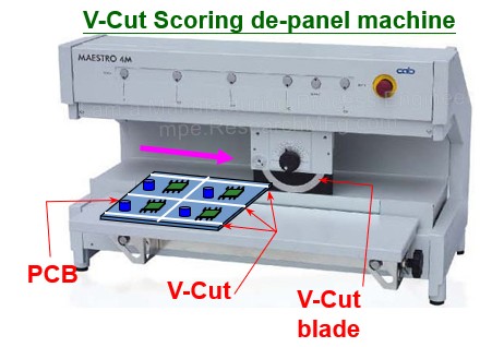
As mentioned earlier, the primary purpose of designing “V-cut” is to facilitate the separation of the circuit board after assembly for operators. During PCBA separation, a commonly used tool is the “V-Cut Scoring Machine” (as shown on the left diagram). Operators align the pre-cut V-grooves on the PCB with the disc-shaped blades of the Scoring machine and then push it forcefully. Some machines come with an automatic feeding design, where a simple button press will move the blade automatically and cut the board at the V-Cut positions. The height of the blade can be adjusted up and down to accommodate different remaining thicknesses of V-Cut. (Note: Besides using V-Cut Scoring for PCBA separation, there are other methods such as Routing, stamping holes, etc.)
While it’s possible to manually break the V-Cut on the PCB, I strongly recommend against doing so manually. Manual handling can cause the PCB to bend due to the point of force application. This can easily result in the cracking or micro-cracking of electronic components on the PCBA, especially for components like capacitors and BGAs, ultimately reducing product yield and reliability. Some issues may only become apparent after a certain period of usage.
Reference Articles:
- PCB Edge Trimming – V-Cut Depaneling Machine
- Video: V-Cut PCB Depaneling Machine Operation
Design and Usage Limitations of V-Cut
Although V-Cut allows us to easily separate panelization into individual boards and remove the board edges, there are design and usage limitations to consider.
Firstly, V-Cut can only cut in a straight line, and it’s a one-shot operation. In other words, V-Cut can only create a single straight-line cut from start to finish. It cannot make turns or change direction, nor can it cut in segments like a tailor’s thread.
This is because V-Cut grooves are created using circular saws on the upper and lower disks. Think of it like a carpenter cutting wood. PCB cutting requires extreme precision (measured in millimeters), so it’s not possible to cut halfway and retract the blade. It’s not that it can’t be done, but rather that it’s unnecessary. If we abandon the V-Cut separation process and switch to routing, we can achieve the same result. Typically, for more complex cutting paths, a routing machine is used for separation.
Secondly, PCBs that are too thin are not suitable for V-Cut grooves. For boards with a thickness of 1.0mm or less, it’s not recommended to use V-Cut. This is because V-Cut grooves can compromise the structural integrity of the original PCB. When heavier components are placed on a PCB designed with V-Cut, the PCB may become prone to bending due to gravity. This is highly unfavorable for SMT soldering operations as it can lead to soldering defects like solder bridges or open connections.
Additionally, when PCBs pass through the high temperatures of a reflow oven, the boards themselves soften and deform due to the temperature exceeding the glass transition temperature (Tg). If the V-Cut positions and groove depths are poorly designed, it can exacerbate PCB deformation issues, making it less suitable for secondary reflow processes.

Design and Recommendations for V-Cut Remained Thickness
In general, when defining the dimensions of a V-Cut, we typically specify its remained thickness, which is the residual board thickness between the two inverted V-shaped grooves of the V-Cut. This thickness determines how susceptible the board is to breakage and deformation.
The most common recommendation for V-Cut remained thickness is one-third of the board thickness. However, it’s not advisable to go below 0.35mm as going thinner increases the risk of the board breaking prematurely during the manufacturing process. On the other hand, it’s not recommended for the V-Cut remained thickness to exceed 0.8mm. If it’s thicker than that, a V-Cut scoring machine may not be able to cut it completely in one pass, and it can also accelerate blade wear, reducing its lifespan.
Definition of V-Cut Angles
Lastly, let’s define the angles of the V-Cut. Typically, V-Cuts come in three angle options: 30°, 45°, and 60°, with 45° being the most commonly used.
The angle of the V-Cut determines how much of the board material is removed along the edges. A larger V-Cut angle means more material is eaten away from the board’s edge. Consequently, the PCB traces must be positioned farther away from the edge to avoid being cut or damaged during the V-Cut process.
On the other hand, a smaller V-Cut angle theoretically favors PCB spatial design but is detrimental to the lifespan of V-Cut saw blades used by PCB manufacturers. A smaller V-Cut angle requires thinner saw blades, which are more prone to wear and breakage.
Furthermore, as the board thickness increases, deeper cuts are needed. Therefore, for board thicknesses above 1.6mm, PCB manufacturers generally prefer not to accept V-Cut angles of 30° unless you have substantial influence. Otherwise, it may be necessary to switch to a router cutting design.
Given that router cutting can effectively address most of the disadvantages associated with V-Cut, why design V-Cuts at all? Well, it comes down to cost! In this world, there’s no such thing as something being both cheap and highly effective. If there were, it would dominate the market, leaving no room for alternatives, right?
Post time: May-13-2024


